Basic principles of PCB assembly: Through-Hole vs Surface Mounted
There are two methods of placing components on a printed circuit board (PCB). The first one is Through-Hole Mounting (THM) and the other one is specified as Surface Mount Technology (SMT). At EPR we use SMT as well as THM. Both methods have their advantages and disadvantages. This blog will explain the differences between SMT and THM and the advantages and disadvantages of both methods.
Through-Hole Mounting (THM)
Through-hole mounting is kind of the predecessor of Surface Mount Technology. The through-hole technology is being used since the introduction of the second-generation computers. Through-hole mounting replaces the old point-to-point construction as shown in Figure 1.
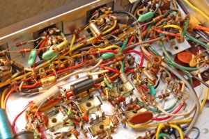
Figure 1: Point-to-point connection. Source: Twitter
Back in the 1950’s, PCBs only had tracks printed on one side of the board. Drills were added to the board in which the leads of a component where inserted. In that way, the components are placed on the empty side of the board and soldered to the copper on the tracked side of the board. In a later stage boards with tracks on both sides, as well as tracks on inner layers of a PCB, were introduced. With that introduction, the introduction of the plated-through holes (PTH) also became a reality. This technology made it possible to connect components to tracks on the inner layer of a PCB.
Axial vs radial leads
There are two types of through-hole mounting components: the so-called axial and radial leads components. With the axial lead components, the leads are placed on both end sides of the component. Radial components have the leads on one end side of the component. Figure 2 displays the two capacitors, where the capacitor on the top side is an axial lead and the capacitor on the bottom a radial lead capacitor.
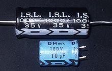
Figure 2: Axial lead (top) vs radial lead (bottom). Source: Wikipedia
Advantages and disadvantages of THM
THM ofcourse has its advantages and disadvantages:
Advantages
- Because there is a much stronger connection between the components and the PCB, through-hole mounted technology is much more reliable than surface mounted technology. For that reason, most connectors are still using THM. It is also the reason that THM is still used a lot in applications for the military and applications that cause a lot of stress or fast acceleration on a PCB.
- Because through-hole mounted components are a lot easier to replace, it is much easier to test or prototype with through-hole components instead of surface mounted components. Using a breadboard in combination with through-hole components is also an ideal combination for prototyping an application.
Disadvantages
- Through-hole components require a lot of space on a PCB in comparison to surface mounted components.
- Most through-hole mounted components need to be placed manually.
Surface Mounting (SMT)
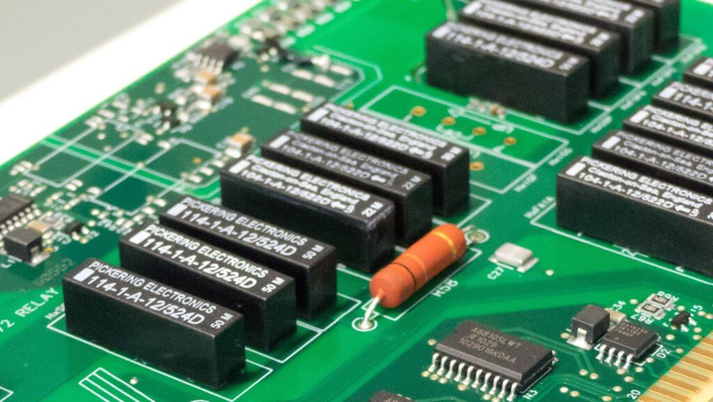
Surface Mount technology was introduced around 1960 and became widely used in the mid-80s. The technology is originally called “Planar Mounting”. The components that are used for surface mount technology have a so-called Surface Mount Packages (SMD). These components have leads beneath or around the package. The big difference in comparison to through-hole mounting is that there is no need to drill holes in the PCB to create a connection between the tracks on the PCB and the components. The leads of the component will make direct contact with the so-called PADs on a PCB. Firgure 3 shows an image of those PADs for SMD components. With the use of a stencil solder paste will be placed on the empty PADs. A Pick and Place Machine will place the components on the PADs covered with solder paste. When all components are placed, the PCB and components will go through a Reflow Oven or, in our case, a Vapor Phase to be solderd on the PCB.

Figure 3: PADs on a PCB. Source: vakits.com
There are many different types of SMD packages with different shapes and made of different materials. These types of packages are divided into different categories. The category “Rectangular Passive Components” includes mostly the standard SMD resistors and capacitors. The categories “Small Outline Transistor” (SOT) and “Small Outline Diode” (SOD), are used for transistors and diodes. There are also packages that are mostly used for Integrated Circuits (ICs) like Op Amps, Transceivers and Microcontrollers. Examples of packages that are used for ICs are: “Small outline Integrated Circuit” (SOIC), “Quad Flat Pack” (QFN) and “Ball Grid Array” (BGA).
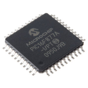
Figure: 4 SMD package. Source: Sparkfun
The packages mentioned above are just some examples of the SMD packages that are available. There are many more types of packages with different variants available on the market.
Advantages and disadvantages of SMT
Like through-hole mount technology, surface mount technology also has its advantages and disadvantages:
Advantages
- SMD components are much smaller than THM components. This will increase the overall density of the board tremendously.
- SMD components can be placed on both sides of a PCB.
- Using a Pick and Place machine for placing the components will reduce production time.
- SMD components are mostly cheaper compared to THM components.
Disadvantages
- Most SMD components are not suitable for high-power applications.
- SMD components are not suitable for prototyping or testing of small circuits.
As you can see both technologies have their advantages and disadvantages. The choice for a specific technology depends on the application and the situation in which a product will be used. EPR would be happy to assist you in making this choice, just to make your product a success.